Hydraulic & Technical Water Engineering
Hydraulic & Technical Water Engineering: a project-specific service for clients who want a technically coordinated water environment rather than a generic installation.
The project scope connects the design brief with site conditions, water movement, structural and waterproofing interfaces, equipment selection, installation access, commissioning and a maintainable operating plan. The final specification is confirmed after project-specific review.
Connected capabilities
Workflow
- Define the user brief, site conditions and operating target
- Translate the brief into design and technical requirements
- Coordinate hydraulics, materials, equipment and controls
- Review construction interfaces, access and maintenance
- Commission, balance and document the operating system
Decision inputs
- required flow and total dynamic head
- static head, friction loss and system curve
- pipe diameter, valves and fittings
- overflow, drainage and isolation
- commissioning, balancing and maintainability
Deliverables
- Project-specific design direction
- Technical decision and coordination points
- Equipment/material requirements
- Implementation and commissioning sequence
- Maintenance and future-upgrade considerations
Technical focus
- Static head and the system curve matter when evaluating variable-speed pumping; simple affinity-law shortcuts can mislead when static head is significant.
- Pipe diameter, fittings and valves contribute to friction losses and shift the pump duty point.
- Isolation and drainage should allow maintenance without destructive access.
- Commissioning should verify actual flow, pressure and operating point against the design basis.
Technical references
Design intent and system context
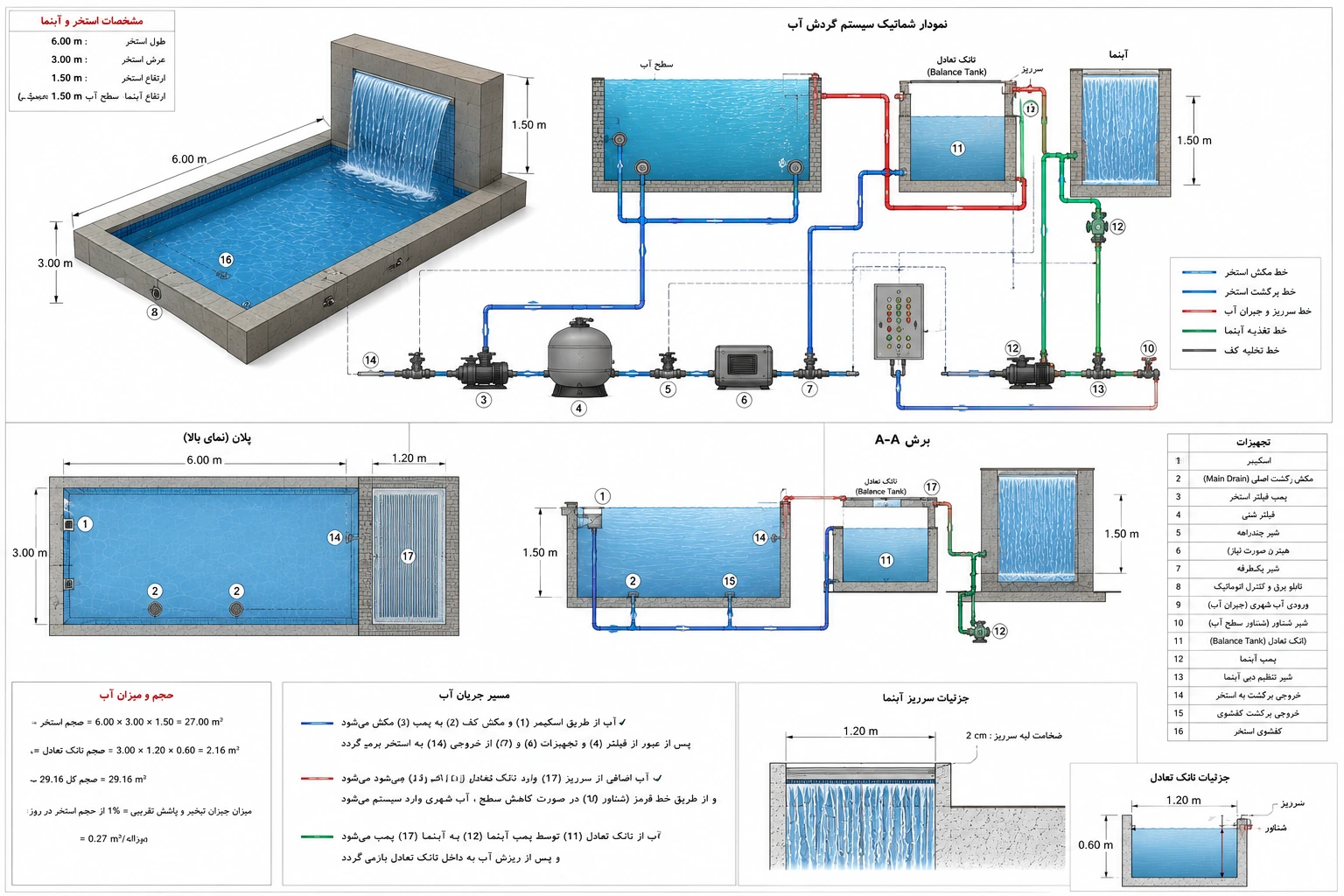
Hydraulic engineering connects the visible water effect to the equipment and concealed infrastructure that make it operate. A technically credible design documents the water route, levels, flow requirements, pressure conditions, pipework, valves, drainage, overflow, equipment location and maintenance access. The calculations and equipment schedule must be based on measured or agreed project inputs rather than assumptions hidden inside a concept image.
Engineering coordination
Pump selection is based on the required flow at total dynamic head, including static lift and friction losses through pipes, fittings, valves and equipment. Pipe diameter influences velocity, friction, noise and energy demand. Suction conditions, priming, cavitation risk, air entry, non-return valves and isolation points must be reviewed for the specific arrangement. Waterproofing design must address substrate preparation, movement joints, penetrations, terminations, protection layers and compatibility between products; water testing should occur at an appropriate construction stage.
Equipment rooms need ventilation, drainage, safe electrical separation, lighting, working clearance and a route for removing heavy components. Labels, isolation valves, unions, access panels and as-built diagrams reduce service ambiguity. Commissioning should verify rotation, flow direction, leaks, control logic, protective devices and the system response to abnormal water level or loss of flow. Final acceptance criteria and statutory inspections depend on the jurisdiction and project type.
Operational performance and lifecycle
A luxury installation should be judged not only at the moment of handover but throughout its operating life. Equipment access, cleaning routes, isolation, replacement clearances, water-quality monitoring and the availability of service information influence the real ownership experience. The design should make routine tasks understandable and prevent concealed components from becoming inaccessible behind stonework, glazing, decking or planting.
Project inputs that shape the scope
- Surveyed levels, pipe routes, distances, access and equipment-room conditions.
- Required flow, operating head, pump curve, pipe sizing and energy profile.
- Suction arrangement, priming, air management, valves, bypasses and isolation.
- Waterproofing interfaces, penetrations, movement joints, drainage and overflow.
- Electrical protection, ventilation, safe service clearances and commissioning tests.
Verification and responsible delivery
Final dimensions, equipment capacities, water-treatment targets, structural details, electrical protection, permits and code compliance must be verified for the actual site and jurisdiction by the appropriately qualified professionals. Manufacturer data and coordinated project drawings govern equipment selection and installation. No generic web page can replace a site survey, engineering calculation, specialist inspection or local approval. Images labelled as concept visualizations communicate design direction only; they are not evidence of completed LWD projects.